Why not load a fully functional computer on a model train? There is so much to know about every inch of the track, and a computer can measure this while running over the track. It should even be possible to add a camera to such a computer and get a live view from the train.
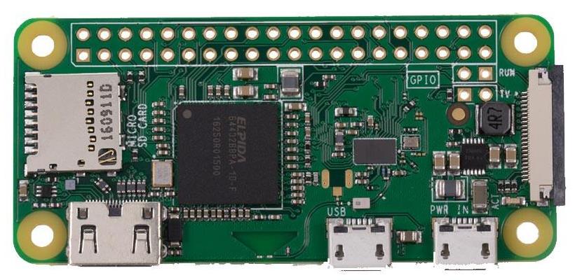
The width of a car is approximately 1 centimeter, and the ceiling of tunnels or the bottom of bridges is typically 5 centimeters above the track, so there is not a lot of space. However, the Raspberry Pi Zero is small enough to fit.
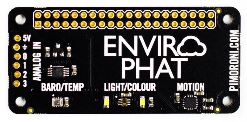
The Raspberry Pi Zero is a small computer with a SD card for storage and wireless network. It can run Linux, and there are a lot of add-on boards available. It even has a very small camera module, smaller than the one used for the normal Raspberry Pi. This project is about the Raspberry Pi Zero and the Enviro PHAT, featuring A/D converters, motion sensors and more.
The width of a car is approximately 1 centimeter, and the ceiling of tunnels or the bottom of bridges is typically 5 centimeters above the track, so there is not a lot of space. However, the Raspberry Pi Zero is small enough to fit.
The Raspberry Pi Zero is a small computer with a SD card for storage and wireless network. It can run Linux, and there are a lot of add-on boards available. It even has a very small camera module, smaller than the one used for the normal Raspberry Pi. This project is about the Raspberry Pi Zero and the Enviro PHAT, featuring A/D converters, motion sensors and more.
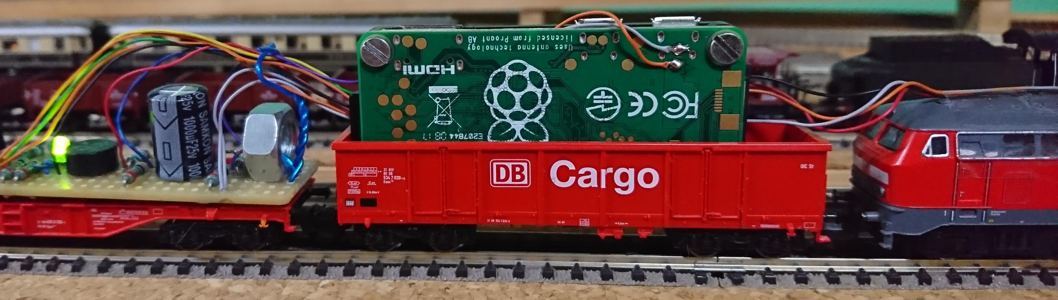
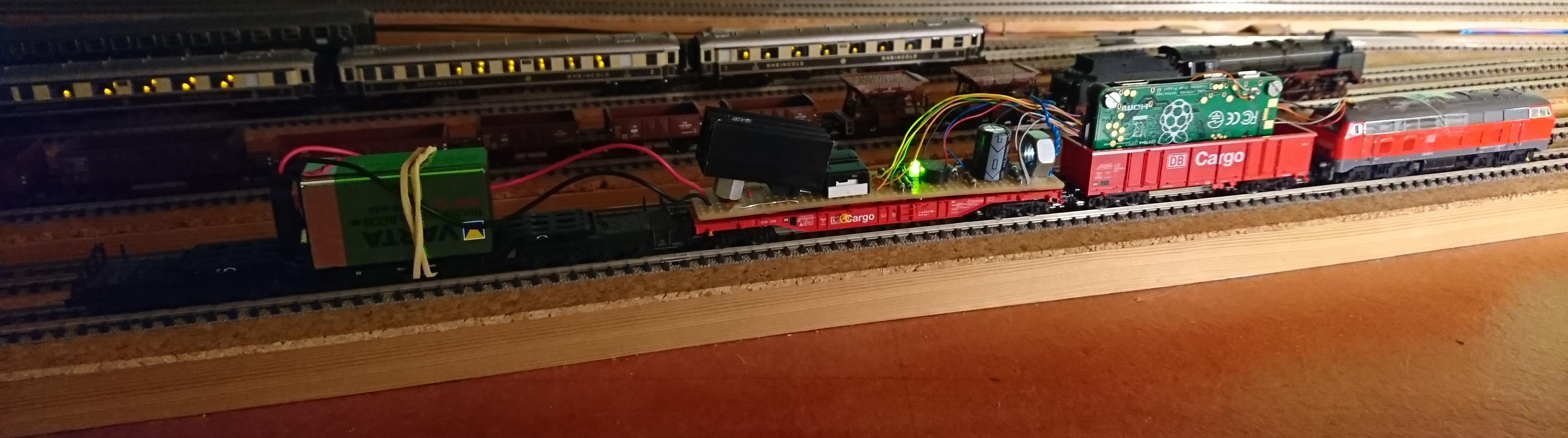
The Raspberry Pi Zero with the Enviro PHAT is small enough to fit on a model train N-scale car. The only thing missing is the power supply.
Model trains take power and control signal from the rails, so a power supply can take the rail signal and convert it into a stable 5 Volt power supply for both the Raspberry Pi Zero and the DC motor in the locomotive.
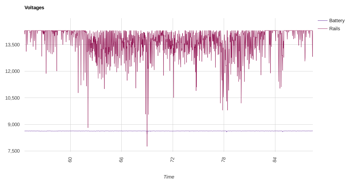
All specifications for the track signal (including voltage levels) are public. See www.nmra.org for details. Expect rail voltages between 10 and 25 Volts, typically around 12-15 Volts.
The power supply is backed up with a 9V rechargable battery, so dirty tracks and bad electrical connections won't give problems.
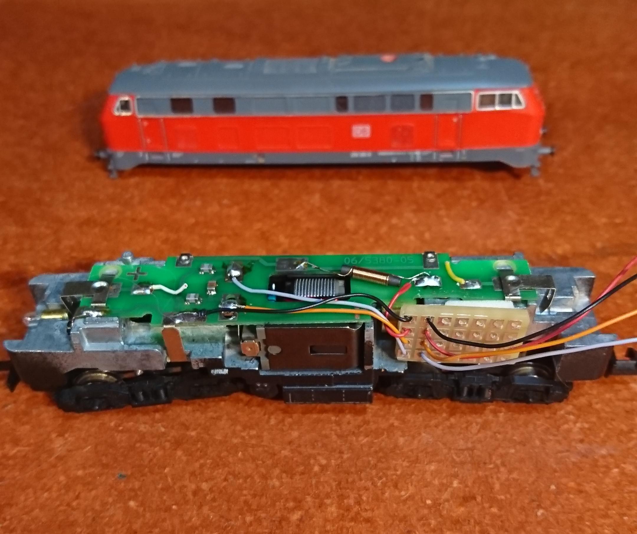
Locomotives prepared for DCC decoders have the connections ready for rail pickup and motor input. Just remove the casing and extend the wires.
Model trains take power and control signal from the rails, so a power supply can take the rail signal and convert it into a stable 5 Volt power supply for both the Raspberry Pi Zero and the DC motor in the locomotive.
All specifications for the track signal (including voltage levels) are public. See www.nmra.org for details. Expect rail voltages between 10 and 25 Volts, typically around 12-15 Volts.
The power supply is backed up with a 9V rechargable battery, so dirty tracks and bad electrical connections won't give problems.
Locomotives prepared for DCC decoders have the connections ready for rail pickup and motor input. Just remove the casing and extend the wires.
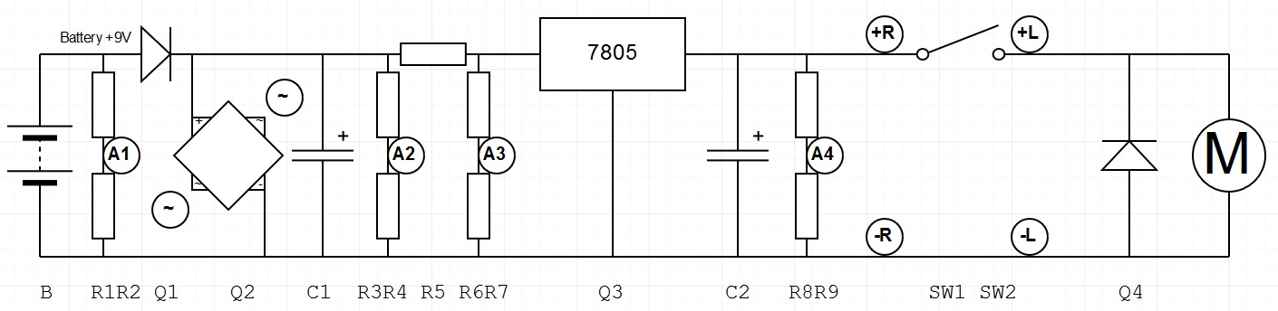
Then build the power supply. Simply send the track signal through a rectifier, smooth it with a capacitor, send it to a 7805 voltage regulator with a heat sink, as it will get quite hot.
The tricky thing is attaching the power supply to a car and making sure it doesn't derail or simply tilt and fall off the tracks, taking the entire train with it. Some weight is required over the wheels, a nut (from a bolt) can give weight in one end, while the heat sink will act as weight in the other end of the power supply circuit.
The wires have to be thin and flexible. The types used inside the locomitive can be bought as "decoder litze", and such wiring is used in this project.
Besides the wires for track signal and power output (times two, one for the raspberry and one for the locomotive) there are also wires for the A/D converters. Since there are four of them, it is possible to monitor track signal quality, battery level, power consumption (through a shunt resistor), heat sink temperature (with a NTC or PTC attached to the heat sink) and more.
Remember to put a voltage divider before the A/D converter, so the measured signal will be max. 3.3 V DC and not overload the converter.
It is practical with a simple on/off switch for both the battery and the locomotive until these functions can be controlled from the raspberry.
The raspberry itself should not be doing anything else than continously reading the sensors and sending data to a dabase on another computer via wireless network. This other computer can then be used to view the incoming data in real time.